I have wanted a diesel motorcycle for a long time. The first one I ever saw in the flesh was a Robin (not the red breast or Reliant type!) single cylinder, on its way to the Dragon Rally in Snowdonia in early February 2000. At the time, I didn’t know what it was, but thought that it looked “interesting”. It was only when I saw a photograph, some years later, that I realised, “that is what I saw at the Dragon Rally”. I have since seen them with cooling fans and huge ducts but they didn't look quite right..to me at any rate. The Robin looked sort of “right”.
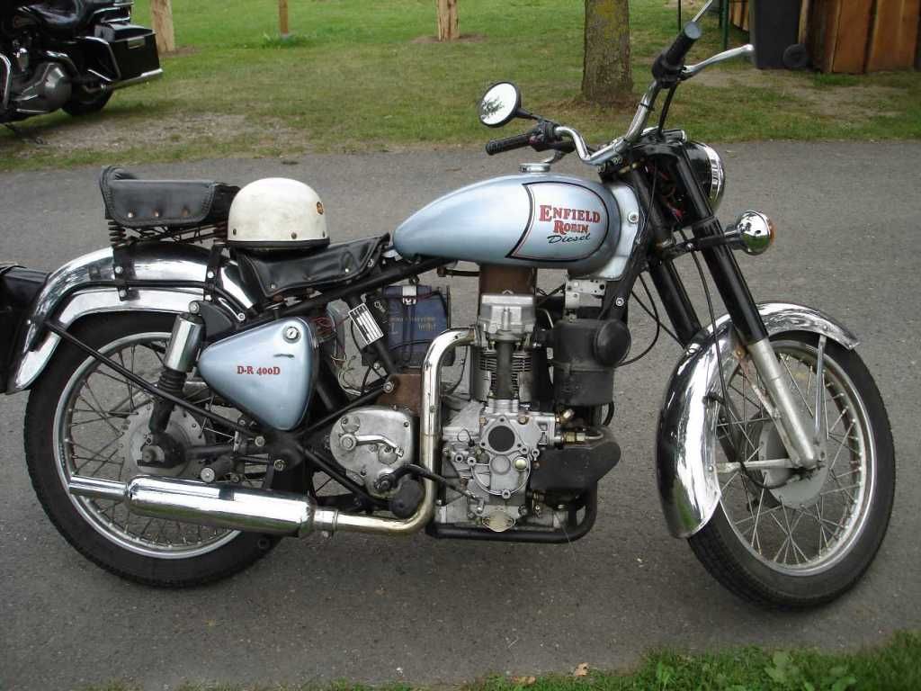
I kept looking at all the adverts and on eBay but nothing ever cropped up. Even so, I didn’t particularly want an engine which had previously been used for mixing 3 of sand and 1 of cement.
About 10 years later, at a Summer rally (once again in North Wales) a chap came along on a Ural fitted with a Daihatsu charade motor. For a long time I looked around for both a Charade motor and a Ural with a knackered engine. After all, that was no point in getting one with a decent engine because the engine wasn’t needed. Urals are plentiful enough but not cheap any more. The Daihatsu Charade engine (and the car) used to be in plentiful supply (it was the first of the mini diesels from what I remember), and as they have not been made for some years, they are now rarer than hen’s teeth.
A little research on the Internet showed that it was possible to put an inline 3cylinder engine into a Ural (and various other motorcycle) frames but was often necessary to lengthen the frame. I didn’t particularly want to do that and further delving showed that was why many people opted for frames with no cradle such as BMW K100, MZ and Triumph Tiger. However I didn’t particularly want to use a chain or belt driven motorcycle gearbox and I liked the idea of shaft drive. I saw a few (not many at all) BMW K100s with a variety of different engines in. Perhaps that was the way to go. I made my mind up: It had to be BMW K100. Cheap and plentiful, even in good running order. Scrap BMW K 100s are not that uncommon and I managed to pick up (from the Bay of E) a running (but noisy when cold) model, with MOT, for just over £400.
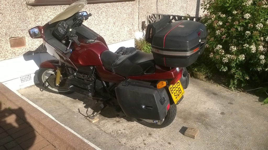
However, I still need an oil burning engine. But which engine?
The search for a Charade motor had taken three months and had not even come up with a sniff. What about a Smart diesel from the Mercedes Smart Car range? All alloy motor. 3 cylinder. In production until 2014 so still available in reasonable supply. Made by Mercedes! 800 cc turbocharged..and virtually the same weight as the original BMW K100 Bavarian lump, just physically taller, so weight would be higher.
Where would we be without the Internet?
The Smart diesel engine in the Smart Car sits over to one side at an angle of about 45°. I think this is purely so that it fits under the floor in the rear of the Smart. I enquired as to whether there was any reason (oil drain from the cylinder head and oil pick up from the sump) could not be fitted upright. I discovered that there were several people who had used the engines sitting bolt upright in aeroplanes a few have built various specials and a couple of motorbikes.
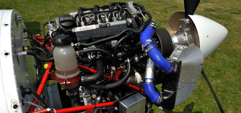
Eva Trak did it vertical too.
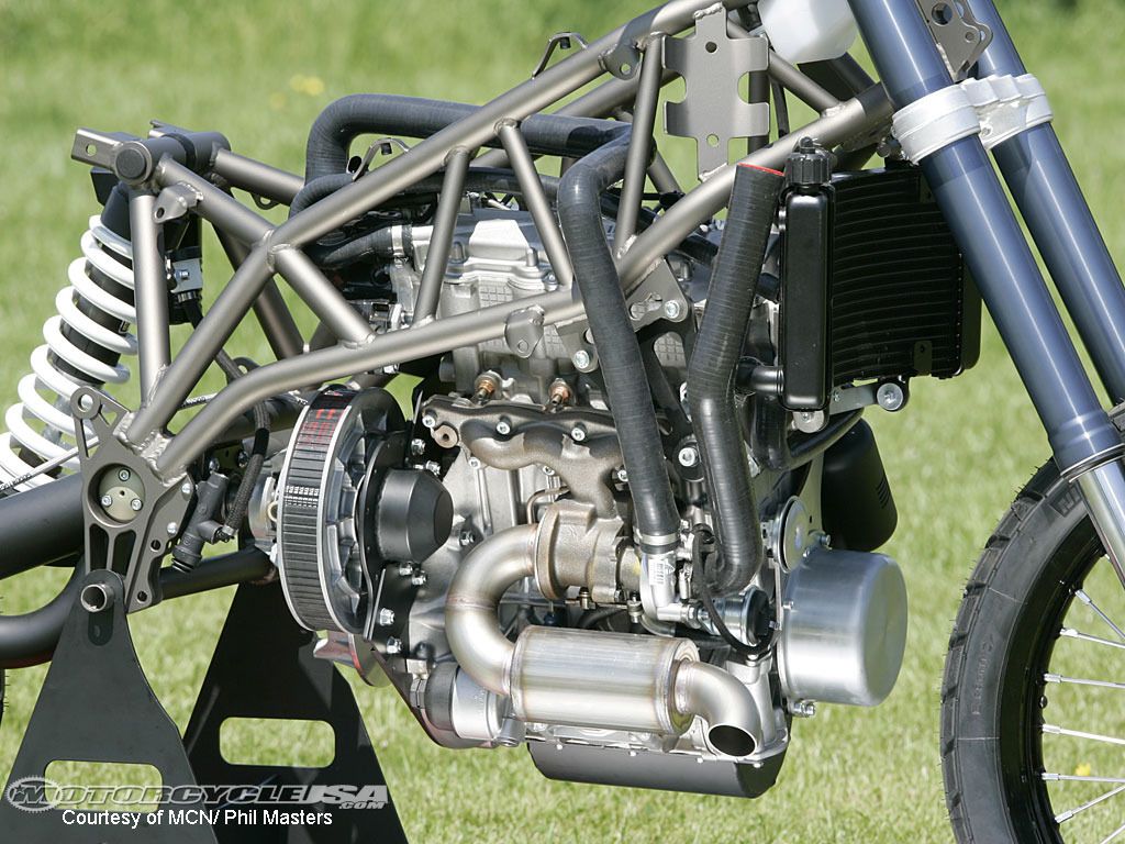
That is good enough for me. One chap has fitted it slanting as in the car but has had to counterbalance the engine with the battery and toolbox. Not for me.
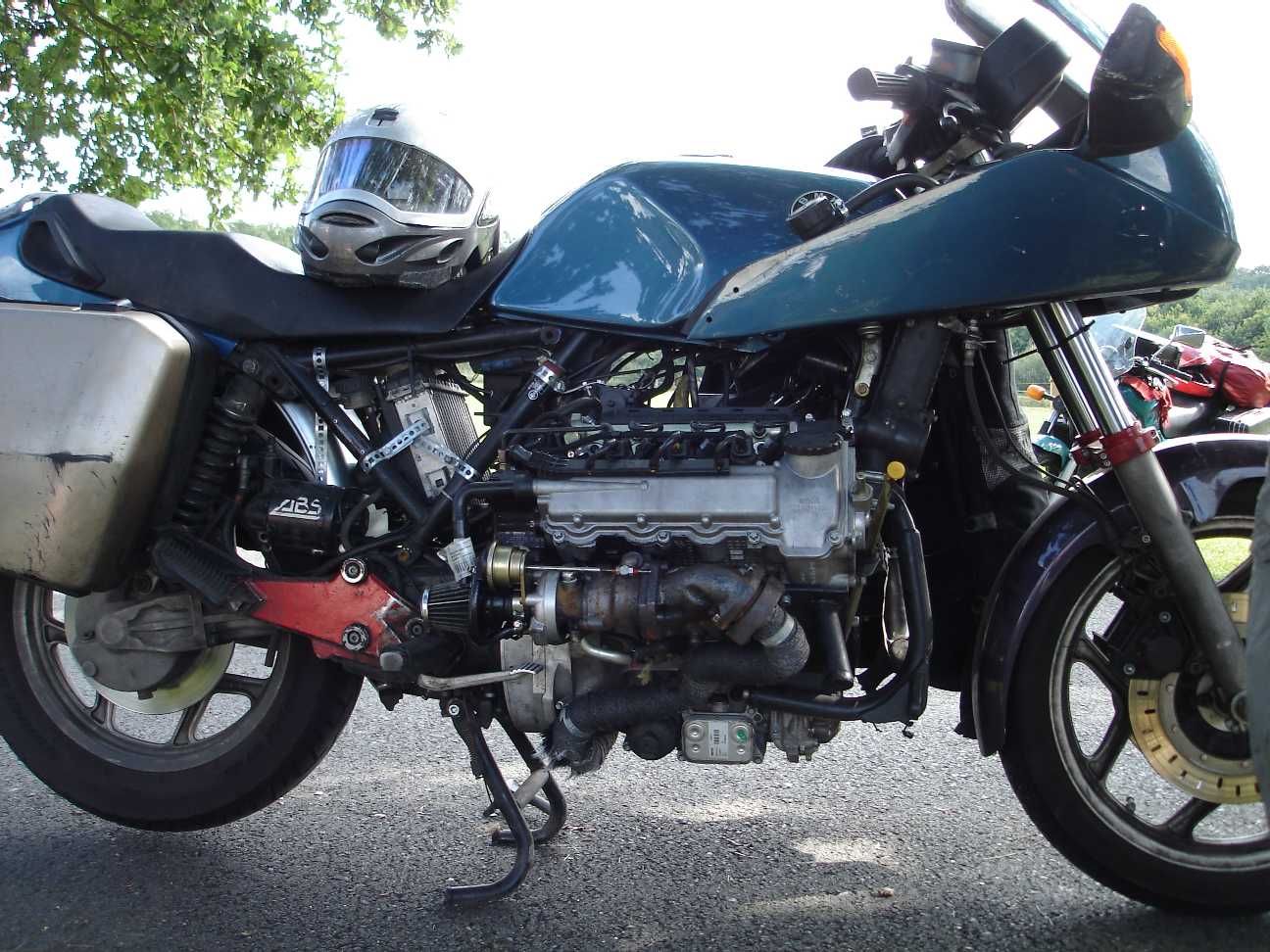
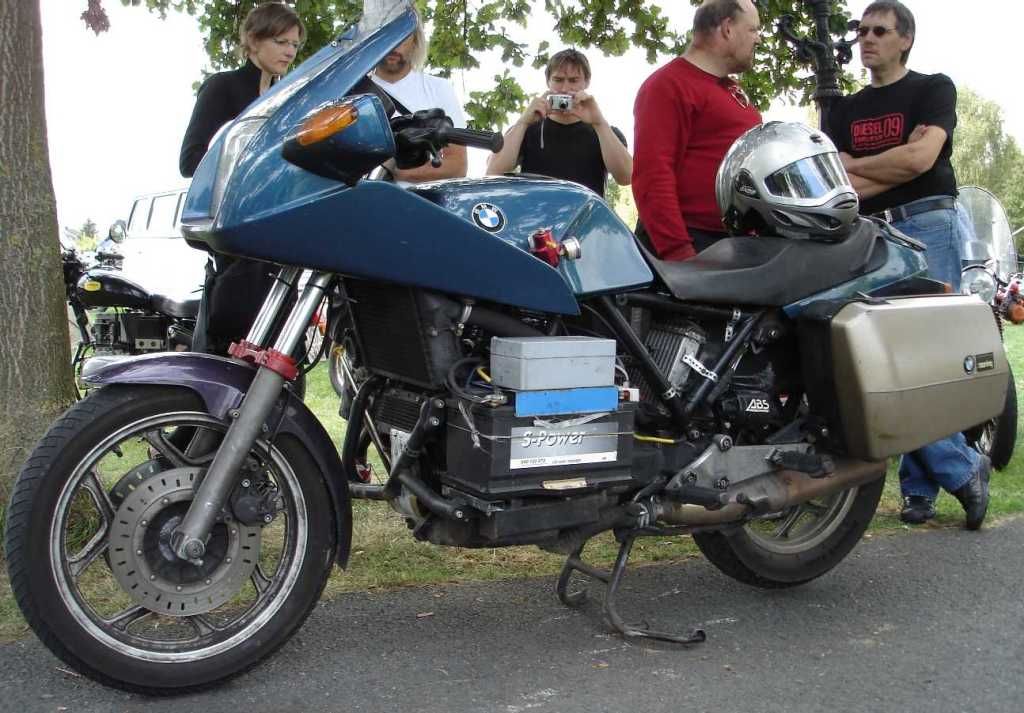
Unfortunately, details are really thin on the ground(apart from lots of useful photos) but a Facebook page from a chap in Lithuania, “Diesel Motorcycle Garage” has proved to be a fantastic source of photographs and ideas.
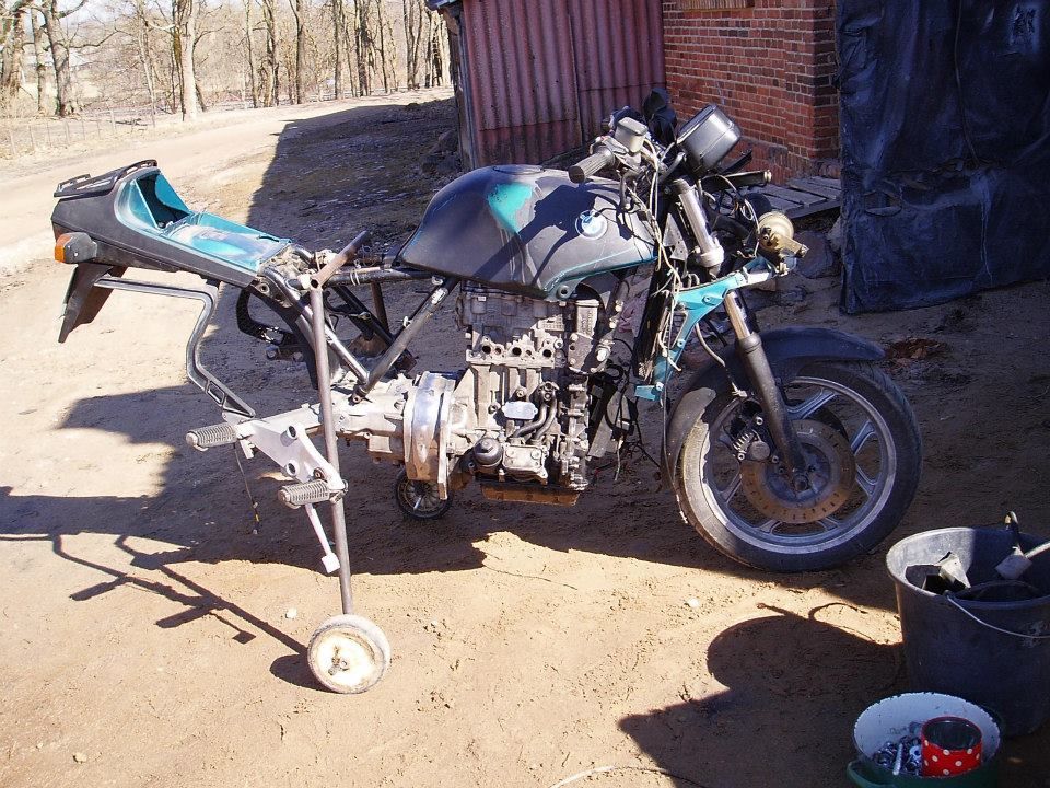
The die was cast. A Smart CDI it was to be. FrankenBrick.
Ideally, I wanted a running car so that I could take the parts that I wanted and see how it all went together. However another three months only came up with cars from just under £1000 to £1500 (and dearer) but even then with almost 200,000 km on the clock and old. I know that diesels are very long-lived but I didn’t want to tempt providence. I did find a couple for 1500 quid, but they were 1998 models and obviously getting a little long in the tooth now.
Eventually, I did a deal with a breaker in Dorset (via eBay) who originally wanted £1800 for a 2009 engine but did a deal for 1150 with alternator, starter, injection and turbo. It meant I didn’t have to get dirty or get rid of the empty shell which was a bonus although I might have been able to sell wheels and seats etc. Could I be bothered? No!
I then needed a loom and an ECU (more about ECU later). However not knowing a fantastic amount about diesels (more than the man in the street but not as much as an expert) I later discovered that I would also need a Glow Plug relay and the Throttle Body and adapter or so I thought…I was wrong, Throttle Body isn’t needed, but fortunately I returned it for full refund. Excellent supplier but then he did sell me the loom and throttle pedal instead.)
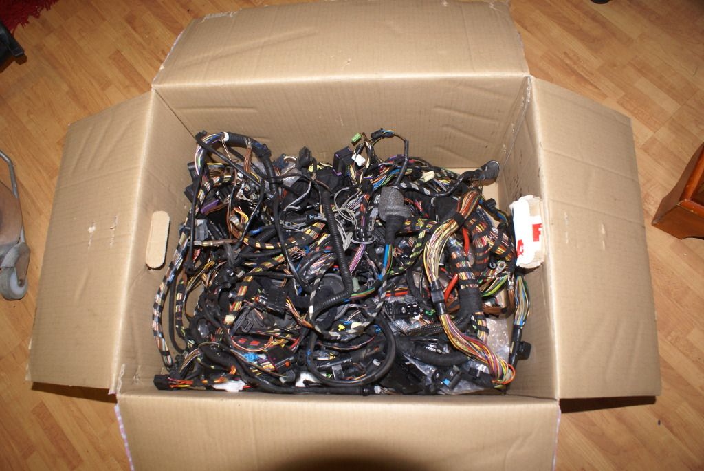
In the end it transpired there is no need to fit quite a few car bits?: Throttle body or Mass Airflow Sensor or Exhaust Gas Recirculation gubbinge (an emission control thing to comply with EU regs) . Oh well, we live and learn. At least I would have an engine in pristine condition with under 50,000 km on the clock.
And so, on Christmas Eve morning 2015 Father Christmas arrived with a 2009 Smart engine on a pallet. It was going to be fun few Xmas holi-days. I was going to learn a lot.
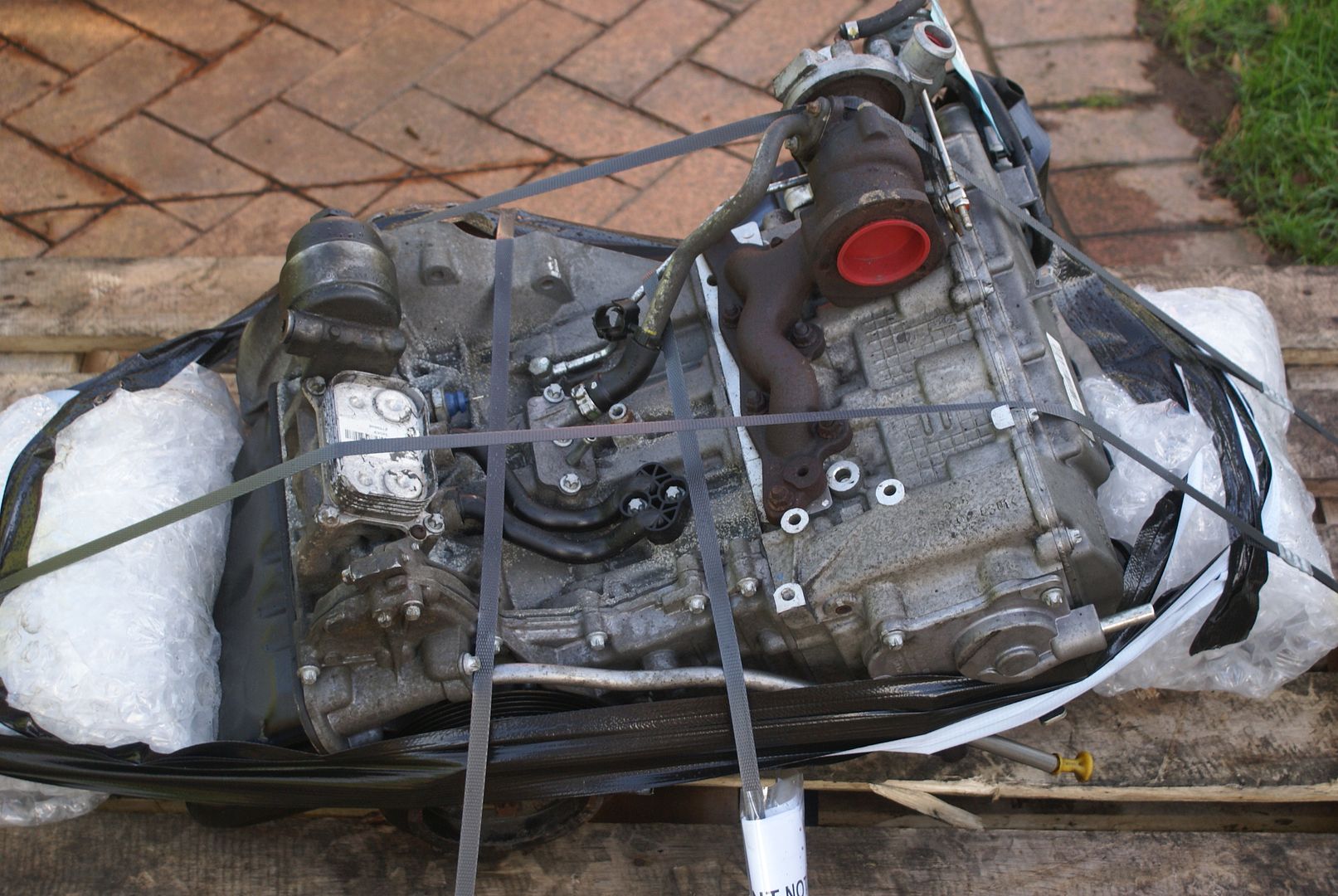
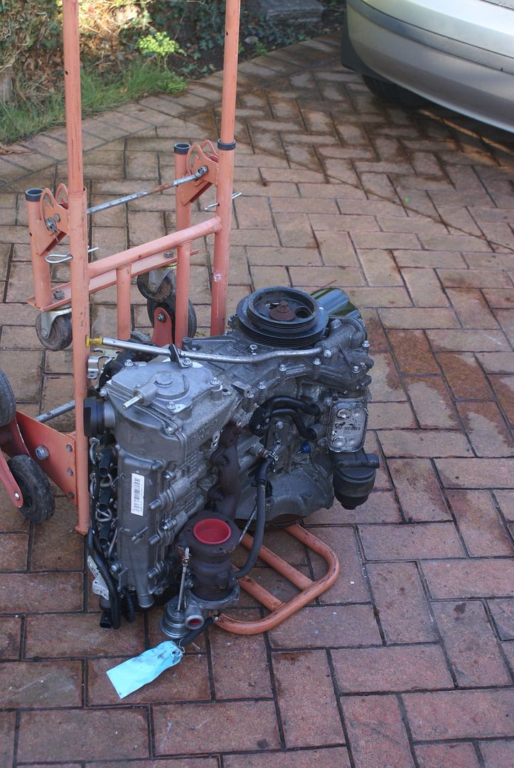
The BMW was stripped and the engine disposed of on eBay for 99p. A bargain for someone. However it did save me taking it to the tip which would have been a shame because although it was a little noisy when cold, it was a very good starter and quite a good runner.
Before the BMW engine went to the tip, I made a note of the dimensions surrounding the clutch location particularly with regard to the distance from the face of the gearbox to the face of the “clutch basket”. This was to make the design of the BMW/Smart adapter plate much easier. Unless the clutch (which is of course attached to the engine) is in exactly the same place in relation to the gearbox, when it is on the Smart engine, the clutch won’t work as the operating pushrod will be too long or short and the clutch friction plate could bind or fall out!
The BMW engine has a cast sort of bell housing between the gearbox and the engine. It is 100 mm thick (from engine to gearbox) and this would be replaced with an adapter. The way the adapter is made is to make a plate to fit the engine, another plate to fit the gearbox, and then join the 2 together. Getting the gearbox input shaft lined up with the centre of the flywheel is a task that has to be overcome but more of that later.
There is a tip here: if ever you are making sketches of things, get yourself a pad of Graph Paper. It is much easier to make reasonable scale and coherent drawings when you have guidelines to follow than it is when the pencil is swirling around over a large blank sheet of paper.
Tip 2: use a soft pencil and get yourself a nice soft eraser (I was going to say “rubber” but in case anyone is reading this in the United States, you know why I used the word eraser!). That way, you can move things around and readjust.
The Smart engine face of the adapter, the front of the adapter (although I didn’t have the Smart gearbox) is reasonably straightforward. It requires a mounting ring 250 mm inside diameter and 290 mm outside diameter with a bump in the periphery to take the starter motor and a bit of a scallop on the outside (to take something previously it would seem on the car but nothing on the bike so it wasn’t needed.)
The gearbox mounting plate end of the adapter however is not so straightforward as it isn’t a flat face unless the gearbox is stripped ..BUT, I did have the good sense of keeping the cast aluminium bell housing which goes between the engine itself and the gearbox of the BMW K 100. It made drawing the shape of the gearbox adapter plate much easier. Place bellhousing on paper. Draw around. Hey presto.
I also kept the spider which drives the BMW alternator via a crush drive because I may fit the motorcycle alternator rather than the huge (and heavy) Mercedes item but fit it on the front of crankshaft . We shall see. One for a rainy weekend perhaps.
I might also fit an electric water pump but the jury is out on that. That may be one for another rainy day later in the build. After making the adapter plate between engine and gearbox, sorting out various piping’s, the only other major job (apart from wiring) is turning the exhaust manifold and turbo upside down.
This is done using an adapter plate (lots of adapter plates on this build!) And once again, pictures are worth 1000 words. It’s necessary to turn the exhaust manifold upside down because if you don’t, it will foul the fuel tank and burn your right knee when you are sitting on the bike. Various bits of plumbing such as the oil feed and drain for the turbo need to be rerouted.
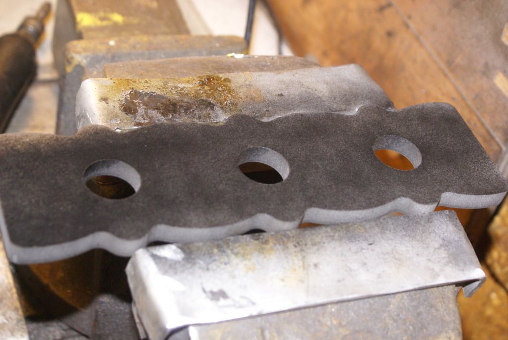
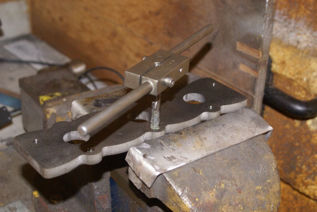
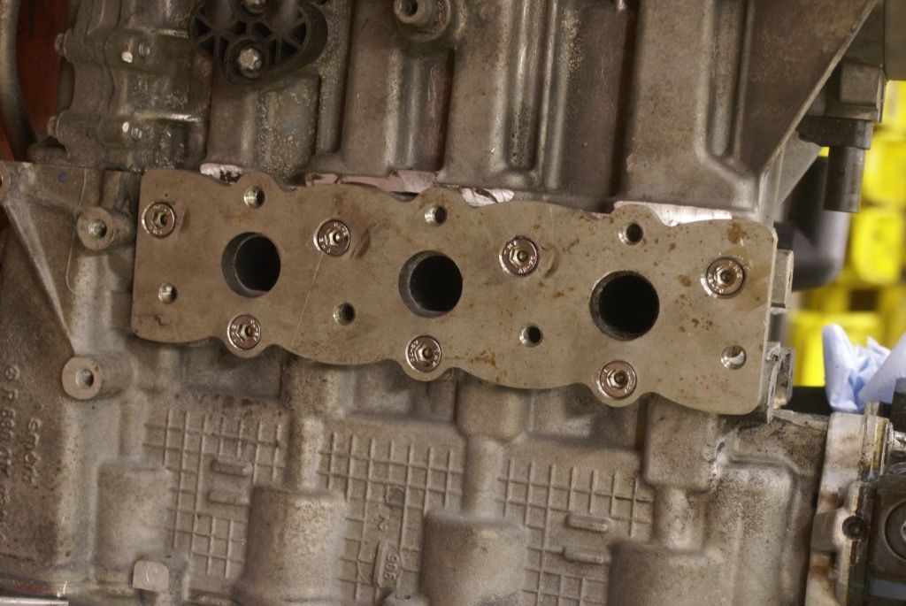
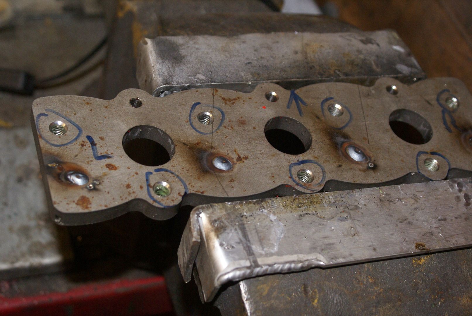
Please note the welded up holes from my cock-up when I thought that the mounting holes were in line. The plate was actually made from 10 mm stainless and the black on it is a waft of black aerosol for me to lay out the positions of the holes marking through the paint. It eventually transpires that 10 mm is not thick enough because when the turbo is turned upside down on the manifold it comes to close to the water pipes which feed the oil cooler. I was never happy with that anyway and always intended to put a heat shield between the two but as it is with a 10 mm adapter plate, it is simply not thick enough. So having got it fitted nicely, I’m going to have another one cut out of 16 mm aluminium (easier to drill!). I’m not going to mess about with jigsaws and milling machines and stuff like that. I’m just having it water cut as I did with the other adapter plates quite simply because it was cheaper than laser.
Here is the Lithuanian one.
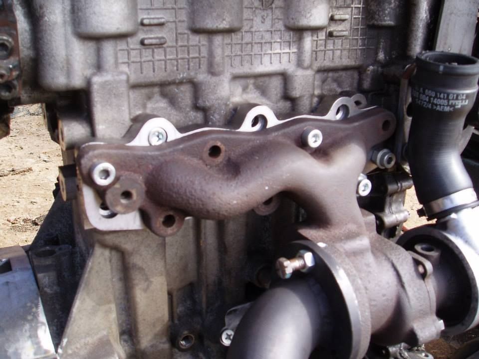
If you look at the Eva Trak photo further up the page, that’s how they did it too
The sump is a wedge shape, left over from when the engine was fitted into the car. This needs chopping off and a plate welding over to make the bottom flat. So it would drain completely also decided to fit a drain plug. The later Smart did not have a drain plug and it was necessary to suck the oil out through the dipstick hole. I wonder how much money omitting the drain plug saved Mercedes?
However my engine wasn’t in the car, it was lying on its side. So as the bottom wedge of the sump was coming off anyway, I simply drilled a hole in the lowest corner and drained all the oil out. Do remember that if ever you are working on the inside of a diesel engine (you will know this already) anything that you touch is blacker than black on a dark night. Make sure that you have lots of cloth to wipe things up, barrier cream to keep your hands clean and preferably also gloves. If you don’t like working with gloves, persevere. When I was in industry, we got to the stage that even with large clumsy rigger gloves, we could pick up bolts and nuts are small as M8. Now, I tend to use Nitrile disposable gloves and good quality barrier cream. I can easily get through half a dozen pairs and night because they do tear but it does mean that my hands don’t look a mess. If I am not doing any kind of slippery greasy job, I very often wear PVC palm nylon backed gloves which literally “fit like a glove”. To my mind, the best supplier of gloves, bar none is Marigold. Yes, okay, you pay more but buy cheap pay twice. Latex gloves incidentally, in my experience, simply do not cut the mustard.
For the same reason of oil drainage I made the sump about 12 mm lower on the left-hand side than on the right-hand side. The grand plan was that the oil would drain to the lowest point. However, it was actually a fruitless exercise because provided the drain plug is on the left-hand side, the oil will drain into the left-hand side when the bike is on the side stand. We live and learn.
 50
50 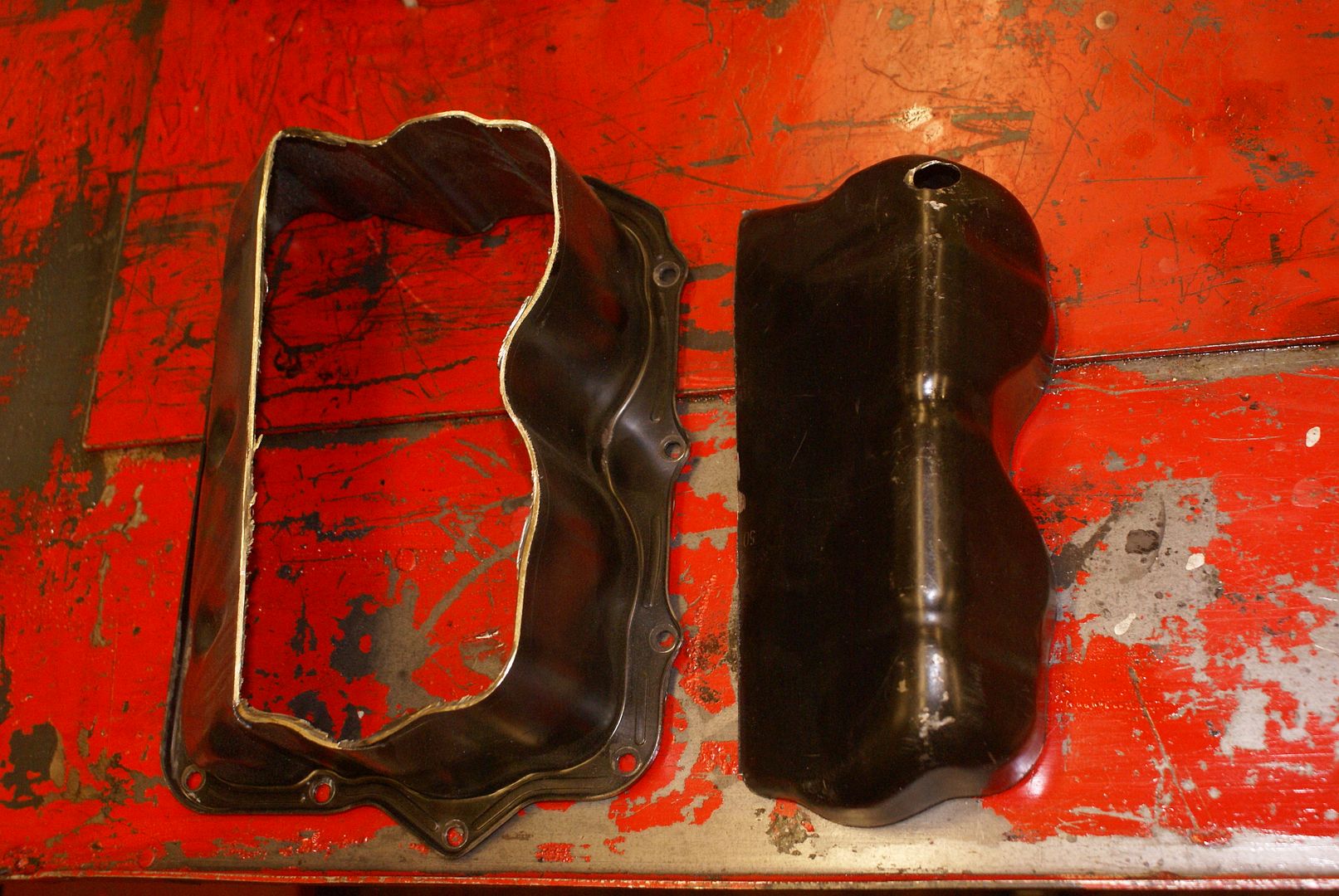
do not forget to shorten the oil pump pickup.
 53 by touchwoodsden, on Flickr
The BMW clutch release arm is notorious for seizing up asit gets covered in road dirt from rearwheel (resolved on later 100 models). I therefore replaced the shaft with a stainless item, renewed the bearings (a couple of quid off eBay) and fitted a grease nipple. Overkill but, for the sake of a tenner all in, what the heck.
Because of the unique way the BMW K100 clutch works, and the fact that the gearbox input shaft has no long nose in the way that a car gearbox mainshaft does (the mainshaft nose that normally fits into the spigot bearing in the flywheel in cars) and the fact that the clutch operating pushrod goes down the centre of the gearbox input shaft (like motorcycles do) means that it is essential to use the BMW K 100 clutch. You just can’t use the car clutch without major major mods. No thanks, I had enough on.
This involved a lot of head scratching and with the help of the photographs from Lithuania, I figured out how it was to be done. However the figuring turned out to be a waste of head scratching time because when the engine arrived from Dorset (A 2009 model which was much later than the Lithuanian one) it transpired that Mercedes (in their infinite wisdom) had completely redesigned the flywheel.
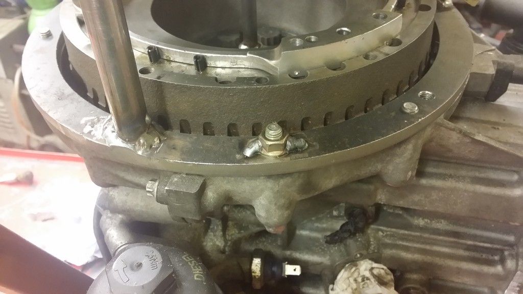
A picture is worth 1000 words and you can see that the outer part of the BMW clutch “housing” (for want of a better phrase) was machined off and set into the face of the flywheel on my engine. Here is my version which was much easier. Good old Mercedes
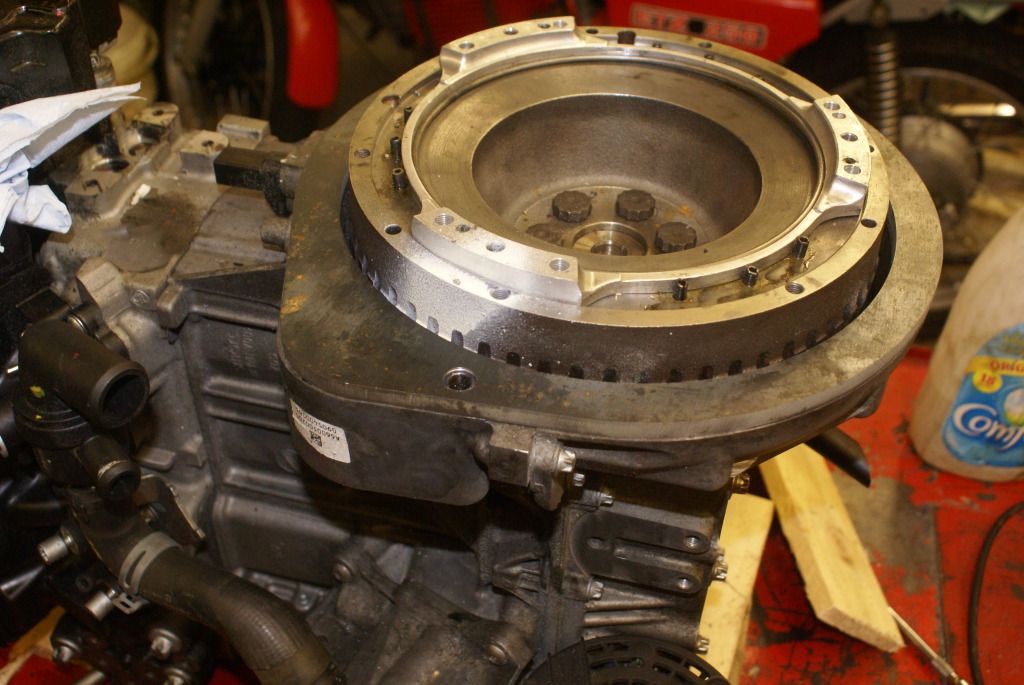
whereas in the Lithuanian model it was inset into the flywheel with a custom made (looks expensive) adapter.
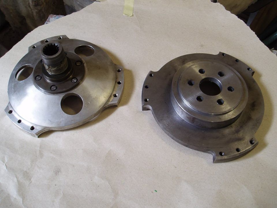
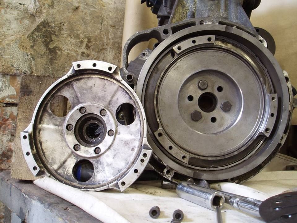
And here is mine sans clutch plates.
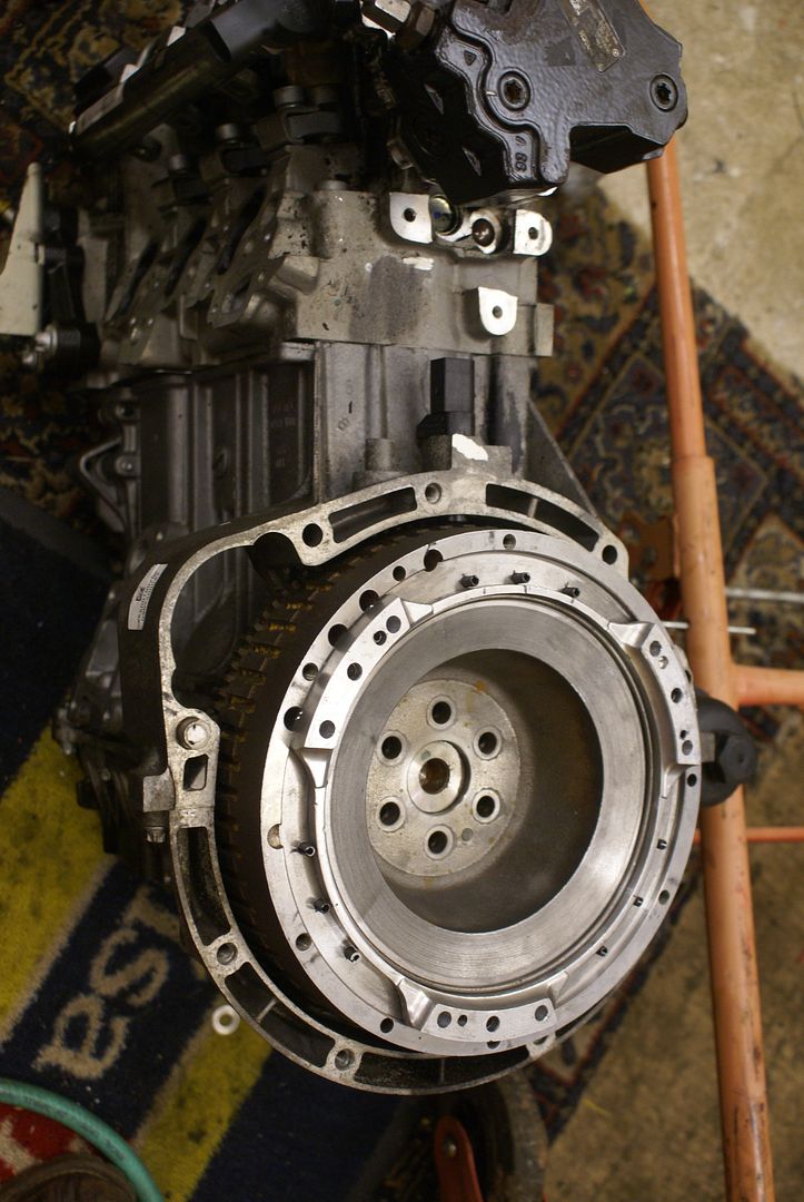
Making adapter plates in general.
Designing templates for adapting an engine to a gearbox or an exhaust manifold, is rather like brass rubbing. If, like me, you don’t have a great source of large sheets of paper or card, then why not do as I did, and use the back of leftover wallpaper. Not white but quite substantial. If it has to be white, buy a flipchart pad: lots of nice smooth white paper.
If you spray the metal part (from which you are going to make the template) with 3M Scotch Mount adhesive, the paper simply sticks to the part and then you can “rub” around the edge with a pencil of dirty finger.
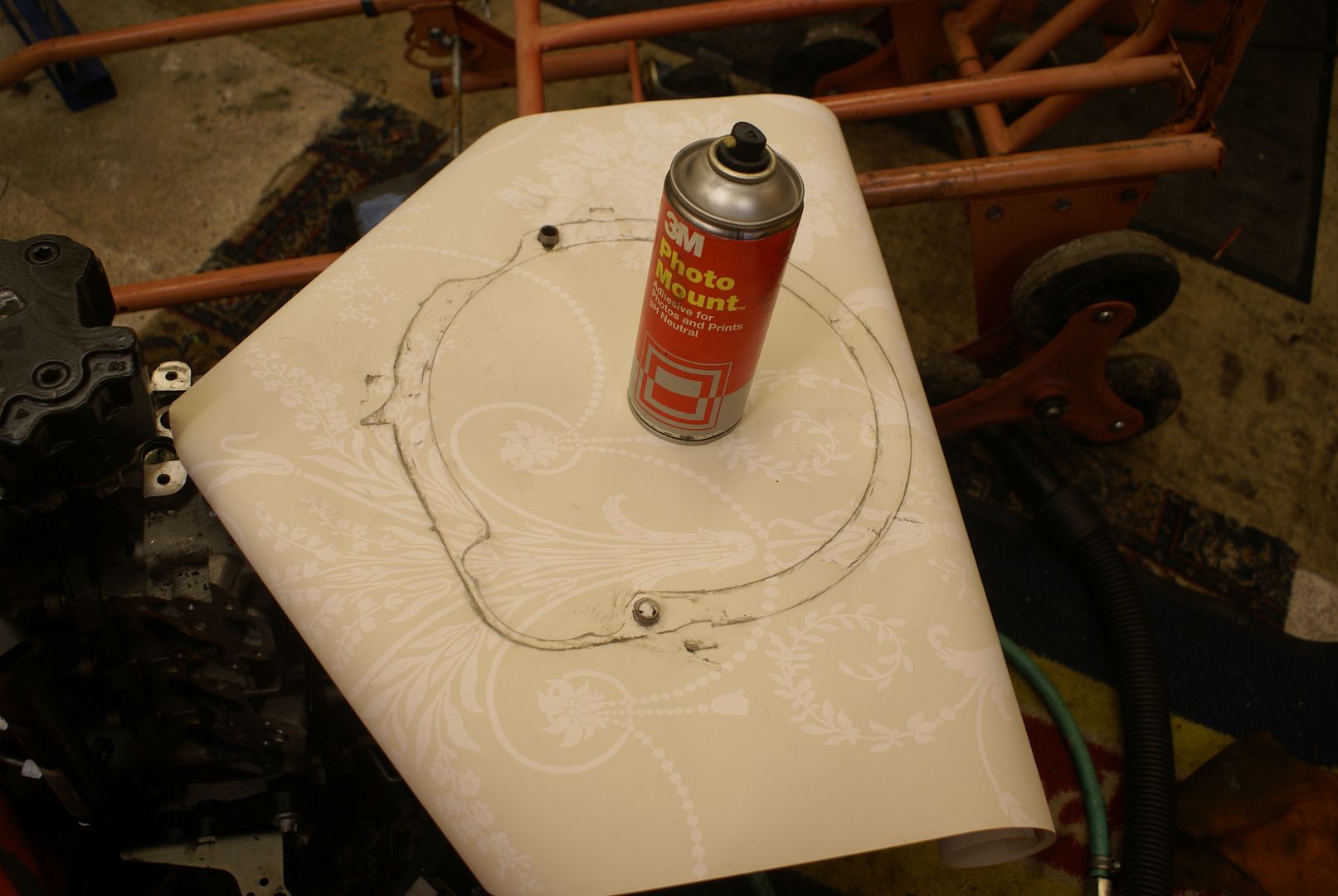
I also used this method when I am drilling holes for the outline, but in the case of the exhaust manifold upside down adapter I used the gasket which was a mistake as it happens. The gasket is made of two 2 leafs of thin stainless steel held together with one tiny spot weld. Get rid of the spot weld using a Dremel, a quick squirt with some Scotch Mount, turned one-piece over, stick together, chop off the corners, and there is the template ready to be laser cut. I decided that the “ears” were not quite big enough so I made those 3 mm bigger. The original studs are replaced with shallow head socket screws which are counter-bored into the adapter plate. The new “upside down holes” tapped M8 into the adapter plate. Simples. Obviously, you then need 2-gaskets, one for each side of the plate. The original gasket could actually have been reused apart from the fact that it was now trashed to make the template.
So, why was it a mistake, quite simply because the holes are too big. It’s better to use the Exhaust manifold as a drilling jig. A lesson learned.
The other thing that you need to bear in mind is that although you would think the centres of the studs were all the same, in actual fact, they are not. For reason, two sets of studs of the lower studs (referring to the photograph again as on the car itself, they are the top pair of studs) are the same and the third set is 1 mm different. Don’t ask me why.

DON’T DO WHAT I DID and simply turn one over on top of the other because the bottom 2 holes around each exhaust port in the photograph are actually offset from the exhaust port so you have to turn them over and back to front.
Once I had the templates on stiff (wall) paper it was then a case of getting them laser cut from the templates.
Backtracking now….
I collected the water cut plates on Monday, 18 January after a wait of a couple of weeks. Really pleased but they do have sharp edges so I spent 15 minutes getting rid of the edges, to avoid cut fingers even though I very often wear gloves.
The plate which holds the water pump outlet on required a little bit of “adjustment” with the spinning abrasive disc (flat flap wheel in an angle grinder) and then fitted perfectly.
There is a water pump bleed which it now is going to interfere with so I might have to rethink how to block that off. It is M12 x fine thread. Although there is enough room to get a grub screw in (I can make a slotted one from a bolt that I have) there is not enough room to get a lot not on the top. A minor tribulation.
Engine to gearbox adapter
Many years ago, I was involved in grass track racing motor cars. We became adept at putting all sorts of huge engines into a variety of different cars and hence, making the adapters to go between the engine and the gearbox. We were not that bothered at that stage about lining things up and provided it went together and ran for the season, we were quite happy. How things change.
What it did however was give me an idea of how the adapter should be constructed.
One important thing is the relationship between the clutch plate and the gearbox input shaft. It has to remain the same. With “normal car-car engine -gearbox” conversions there may be issues with regard to the diameter and number of spines on the clutch plate with the Smart Car K 100 conversion, it is less of a problem. I will explain why.
Between the BMW K 100 gearbox and engine there is an aluminium “housing”. It is 100 mm long as I have said already. (BMW seem to make things in whole numbers of millimetres which is really convenient!). On the photo it says it is 90mm which is wrong.
The distance from the rear face of the original BMW engine to the face of the clutch basket, on the original motorcycle engine is 38 mm. Simple deduction of maths, it doesn’t take Pythagoras to work out that 100 mm minus 38 mm says that the distance between the face of the clutch “basket” on the BMW to the face of the gearbox is 62 mm. so far so good.
Therefore, as long as in the new conversion, the distance between the face of the BMW “clutch basket” to the face of the gearbox, remained at 62 mm, the input shaft would go the correct distance into the centre of the clutch friction plate because it would be in the same position relative to the gearbox. Simples provided you don’t cock things up of course or measure wrong.
When the clutch basket was installed on the Smart flywheel, the distance from the rear of the (now Smart) engine had risen from 38 mm to 41 mm. With an increase of 3 mm. It follows therefore that the new “housing” adapter had to be 100 mm +3 mm =103mm. Simples.
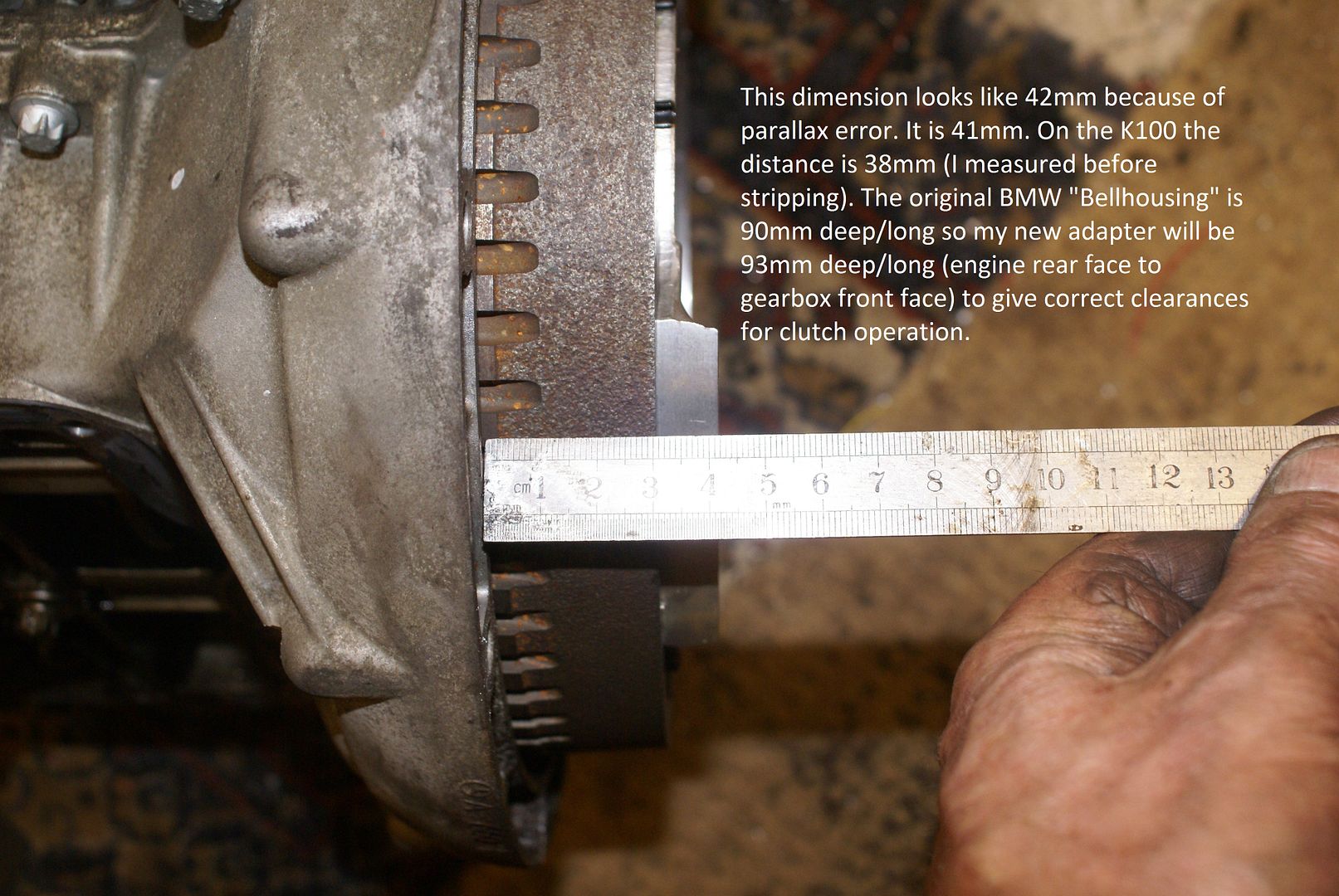
When an adapter plate, there are other dimensions and alignments which are critical or semi-critical.
In order, they are:
1: alignment of the gearbox main shaft with the crankshaft which must be absolutely perpendicular with each other and concentric with exactly the same centreline.
2: the face of the gearbox must be exactly square with the face of the engine.
3: the distance between the engine and the gearbox (i.e. The thickness of the adapter) which I mentioned a few paragraphs ago which is the distance to ensure engagement and disengagement of the clutch without anything binding.
4: probably, the least critical of the dimensions in designing the adapter plate is the orientation of the gearbox in relation to the engine. If the engine is rotated in relation to the gearbox, by a few degrees, it may look a little odd and it may make the engine mountings a little awkward to manufacture but it will still function perfectly well. After all, the engine was originally fitted to the gearbox canteen over at 45°
The adapter plate which amounted onto the engine is 8 mm thick in my case. I decided on 8 mm because it needed to be thick enough to provide plenty of thread for an 8 mm bolt tapped into it but I didn’t want it to be as heavy as it could have been. I chose steel because of cost. Aluminium would have been great but difficult to weld (for me at any rate). The adapter plate which mounts on the gearbox is 8 mm thick so, 100 mm plus 3 mm plus the 16 mm thickness of the 2×8 mm plates means that the distance between the plates needs to be 87 mm. or putting it another way, 87 mm +8 mm +8 mm equals 103 mm. So simples!
You will recall I mentioned about everything being square and lining up.
To make sure that it is square, is easy enough by simply using exactly 87 mm pillars to space the engine adapter plate from the gearbox adapter plate, and mounting the pillars between the two plates. In effect, it would have 4 little legs, each 87 mm long spacing the engine from the gearbox.
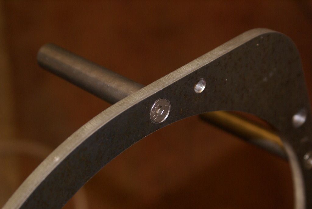
There is actually no reason why the open housing thus created could not be used except that it doesn’t look particularly good and there is a big flywheel spinning around and sticky little fingers do tend to get ripped off if they get stuck into the moving flywheel. Hence, it makes sense to enclose it in some kind of peripheral cover.
Everyone will find their own way of making adapter plates.
Obviously, as the adapter plates have been made each of the plates needs attaching to the relevant part, engine or gearbox. There is no point in trying to measure the position for each of the holes as it easy enough to simply mark through them onto each plate ready for drilling.
On the Smart engine, the majority of the gearbox fastening bolts went through clearance holes in the gearbox into tapped holes in the rear engine block face. These tapped holes are not particularly practical and therefore, I drilled through them 8.5 mm (8 mm clearance) to take M 8 belts. Mistake! I will explain.
I have a piece of 8 mm Silver Steel bar which I turned a point on to use as a centre punch to mark each of the holes. I hardened it (heat cherry red and range in cold water) and then tempered it (heat to dark straw colour and then quenching cold water). The grand plan was to put this in the holes and give it a tap with a hammer to make a mark which could then be centre punch properly. However even the dimmest mathematician will realise that an 8 mm bar in an 8.5 mm hole is going to waggle around a lot.
What I should have done is to drill all the holes mm 8 mm, then mark the holes using my home-made 8 mm centre punch and then, when they were marked, drill them 8.5. We live and learn.
What I did therefore was taken turn PVC insulation tape around my “centre punch” to fill the gap and make the marketing more accurate. It worked.
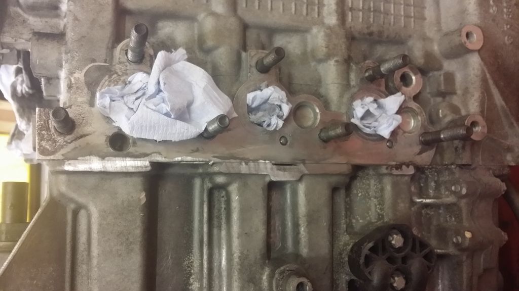
Don’t try to drill the holes at once. The gearbox is located on the engine with hollow dowels although to be honest, they’re not so much a dowel as a piece of tube. First, just drill one whole to take the dowel or, if you have two dowels (mine only had one) remove the dowels, Mark one, drill it, fit the plate, clamp in place, and then drill the other one. Then, with the whole plate secure and clamped to prevent it moving, centre pop through each of the M 8 mm holes around the periphery.You can just see the centre pop in the piccy
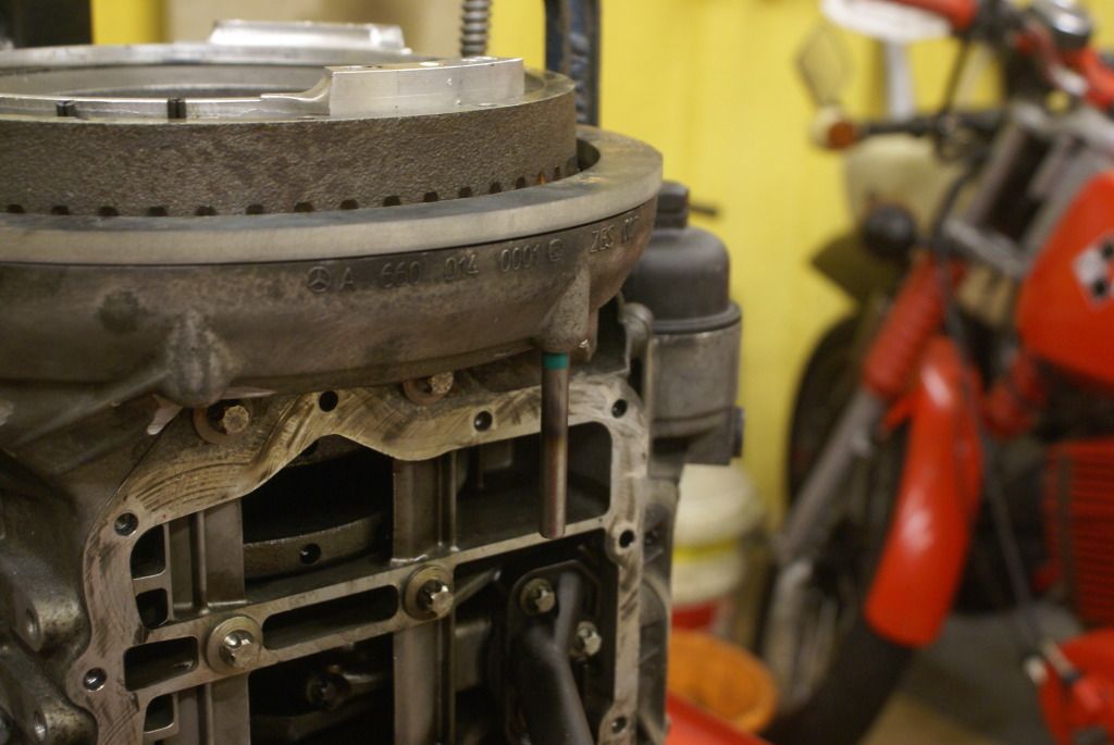
Then remove the plate and drill the holes. Remember, these holes are going to be tapped M 8 and therefore they needed to be drilled just under 7 mm diameter.
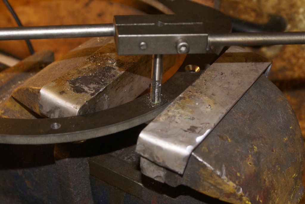
As a rule of thumb, the tapping drill size is the diameter of the thread less the pitch. Hence, 8 mm x 1.25mm pitch needs an 8mm -1.25 mm equals 6.75 mm tapping drill. Simples. It works for me. No comments please.

I have seen a few Smart engine motorcycles and on some of them, the plumbing looks like the inside of a central heating boiler. At some stage I may substitute an electric water pump for the mechanical one (much lighter weight) and put a different alternator on, but initially I’m sticking with the original set up purely because it’s a couple of less jobs that I have to do. Unfortunately, the cooling pipes come out in the wrong direction. I had inspiration with the cooling pipe which goes into the water pump where I turned the inlet manifold through approximately 90° to get the pipes to line up much better. Whilst turned through 90°, although the pipes lined up in a much more logical fashion, the mounting bolts didn’t line up in any fashion at all. I therefore chopped the lugs off and made a plate to retain elbow into the pump. The pictures say it all.
 DSC04227
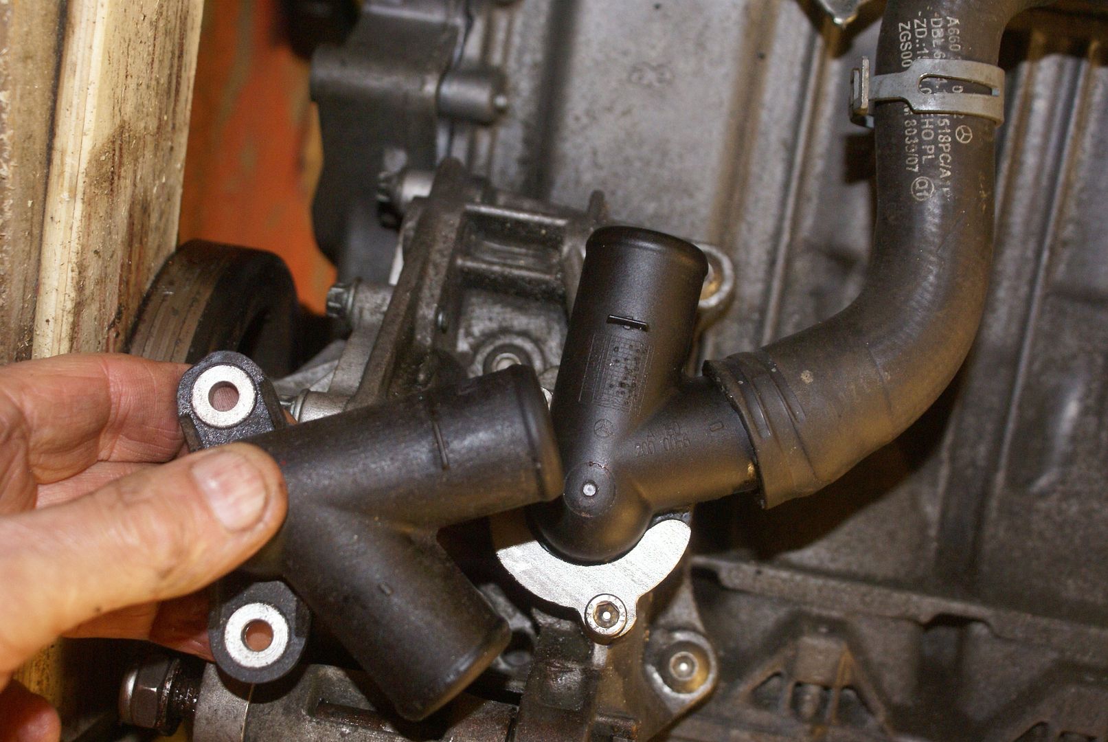
 DSC04229
 Adapter plates revisited
I’m going to go back now to how the engine to gearbox adapter was made. You will recall that I said that it was a bit like brass rubbing. There was a “rub” made from the gearbox face and another rub made from the rear of the engine. The rub from the rear of the engine was superimposed onto the rub from the gearbox and any extra metal needed was added to the circumference of the gearbox rub. Then dimensioned drawings were made from each from which the adapters were then cut. In fact, as I was having the machine cut, I invested 50 quid in having them drawn by CAD which made the cutting much cheaper. I had it done on the Internet from one of these paper job sites. They were finished in under 24 hours.
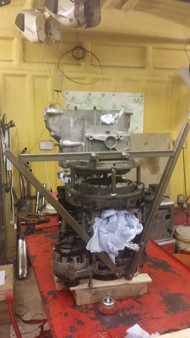
The 4 x 87 mm pillars were then presented to the Adapter Plate around the Circumference. They were fastened to the engine plate using 6 mm countersunk screws to make sure that they were absolutely square.

The engine was then stood on its nose with the flywheel in the air. At this stage, the flywheel doesn’t have the clutch fitted .
I had to line up the gearbox main shaft with the centre of the crankshaft/flywheel. There is a hole down the centre of the gearbox main shaft which is a snug fit on a piece of 10 mm steel. This takes the clutch pushrod as you are now aware that the clutch and whole gearbox input shaft layout is a lot different from that on the car. I cut a length of 10 mm steel and sweated a lump of brass on the end. I turned the brass down to 16.1 mm so that it was a nice snug fit in the centre of the Smart crankshaft.
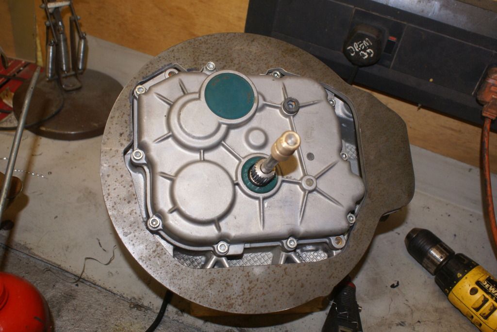
Other people have done this with the dismantled gearbox and a dummy main shaft with the front turned down to 16.1 mm. However, it meant stripping the gearbox and although I have to do it later to put high ratio gears in, I didn’t want even more bits lying around at this stage. I also figured that a piece of 10 mm bar is not going to bend very much with hand pressure only over a very short length.
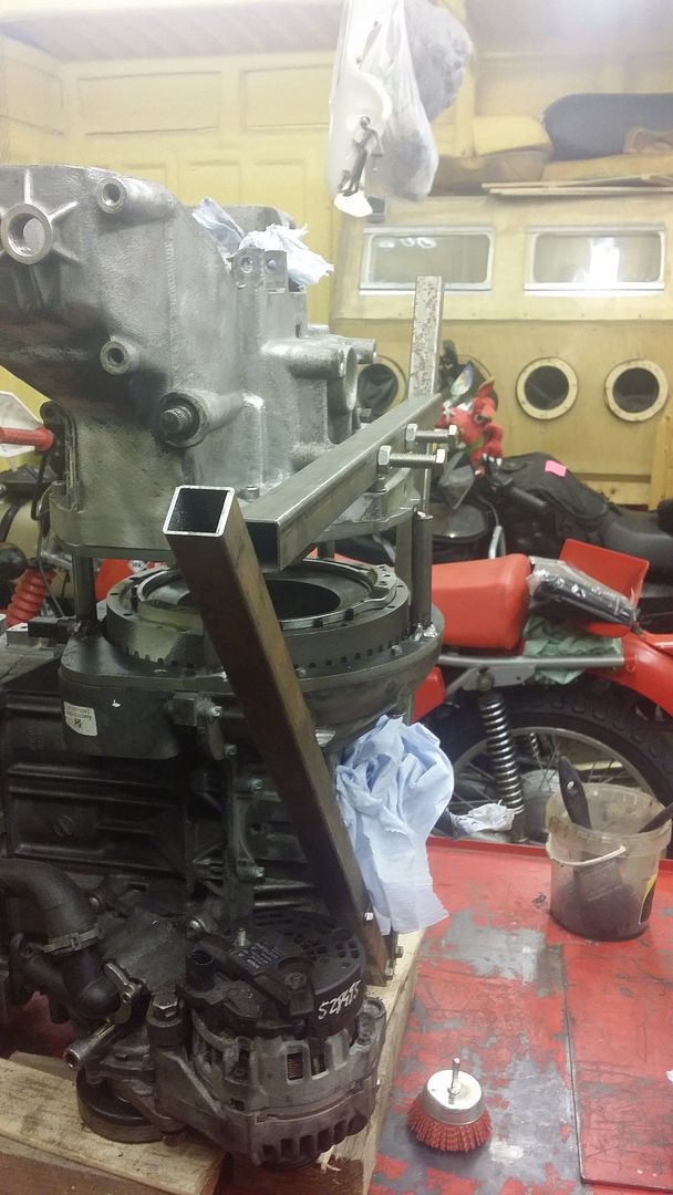
So here we are with the engine sitting on its nose with its flywheel in the air, the engine adapter plate fitted and the 4 x 87 mm pillars sticking up in the air like the pillars of Hercules.
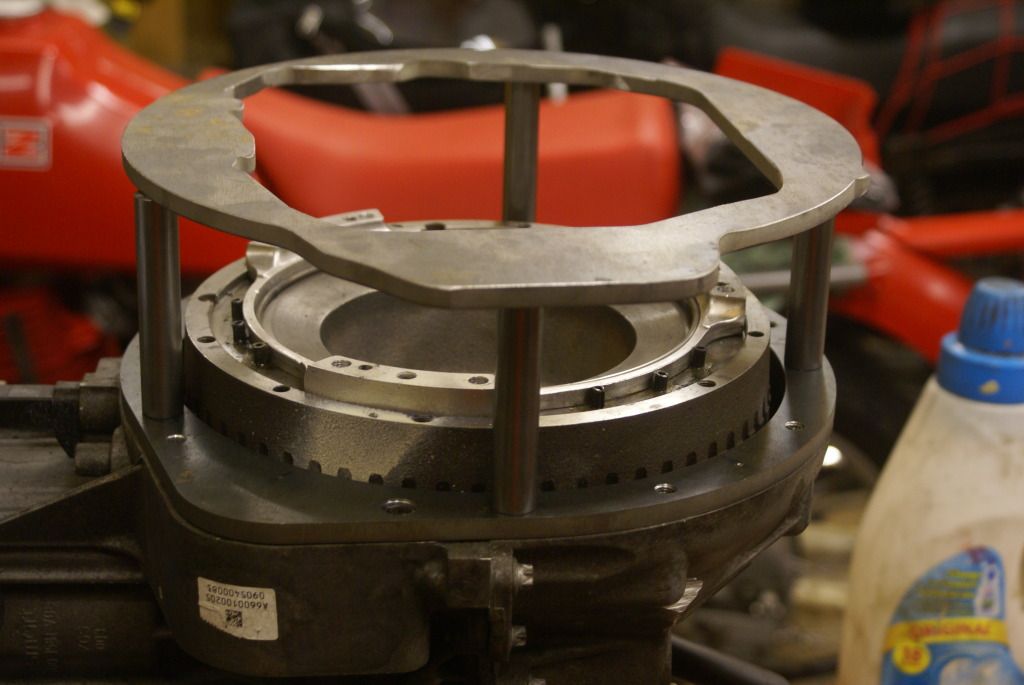
The gearbox with its alignment mandrel (which was trying to fall out) was placed on the top of the engine whilst the distances were checked. The mandrel lined up nicely with the centre of the flywheel/crankshaft although because of inherent play there will quite a few millimetres of movement in all directions which would miss a line the gearbox with the crankshaft. This would lead to some kind of premature failure, possibly the clutch, or even the gearbox. Not good. It had to be concentric within a couple of thousandths of an inch or better. (I will never get my head round tiny measurements in millimetres).
It’s a bit like trying to centre the clutch plate in an ordinary car engine gearbox before putting the gearbox back of the engine. Even if you have a mandrel of the correct size, it’s never absolutely spot on because there is a bit of play. It’s even more difficult with no mandrel and it then a case of moving the clutch friction plate in each direction and engaging how much it needs to go back in each plane in order to be central.
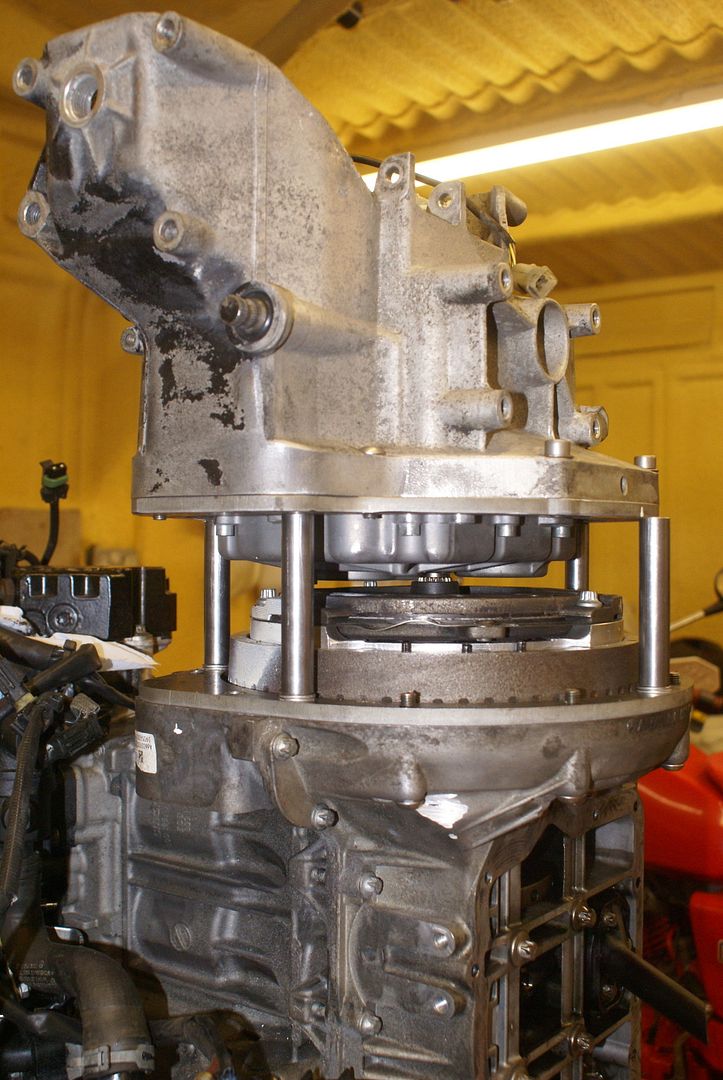
With a conventional engine and gearbox, it doesn’t matter if the clutch and gearbox main shaft don’t align because as soon as the clutch is released, the friction plate will self centre. The gearbox main shaft and the crankshaft have to be absolutely in line so I’m not talking about the whole manufacturing assembly, simply putting the clutch back in. However I am digressing which is not a good idea because the operation of the clutch is so different.
What I needed to do was make sure that I was in the centre of the clearance play in each direction and plane.

So, how did I do it? I pondered this for a long time before I came up with a solution that I hope is going to be sufficiently accurate that the whole thing stays together. I’m satisfied that it’s accurate within a couple of thousandths of an inch. Perhaps I’m being optimistic, but still, I remain optimistic.
So, here we are, we have the engine with its bottom up in the air, the pillars of Hercules are spacing the engine from the gearbox but the gearbox is able to move around in relation to the engine a few millimetres in each direction.
I had recently looked everywhere from my Dial Test Indicator (DTI). It was not to be found and clearly I had lent it to someone and it had never come back. I therefore bought another one from eBay, only 16 quid delivered and a bargain. Would you believe, on the date arrived I then found a box with three of the bloody things in so now, I have 4.
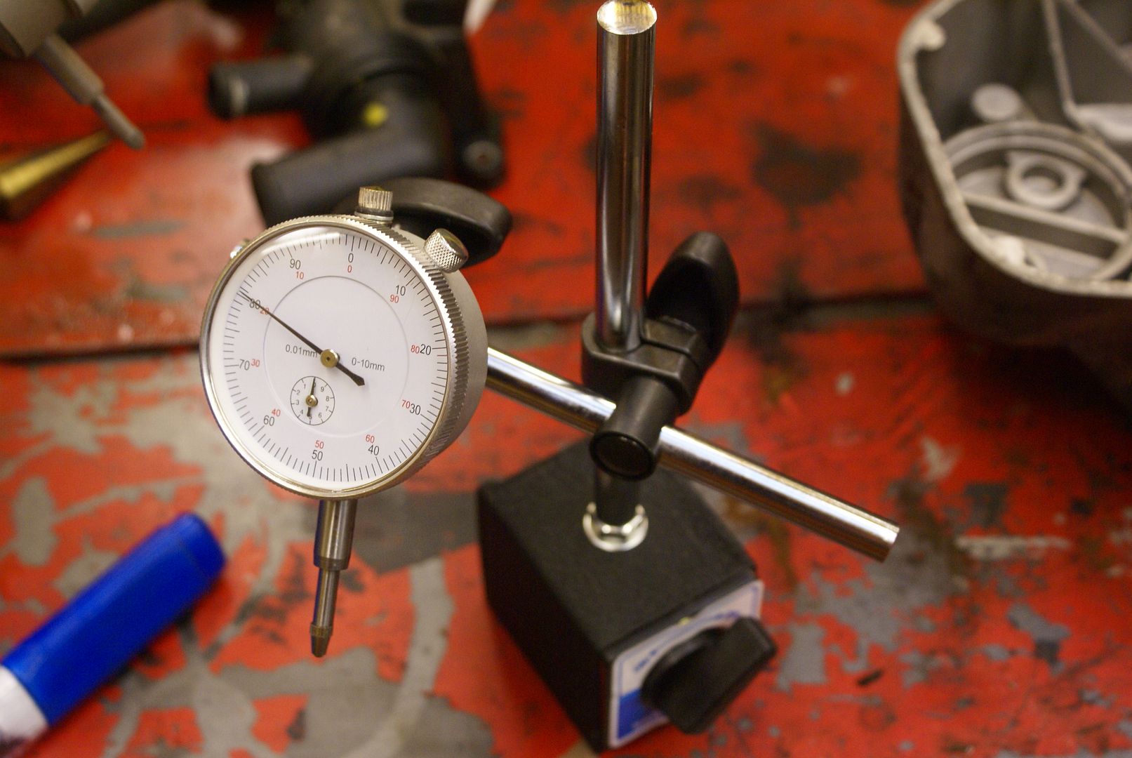
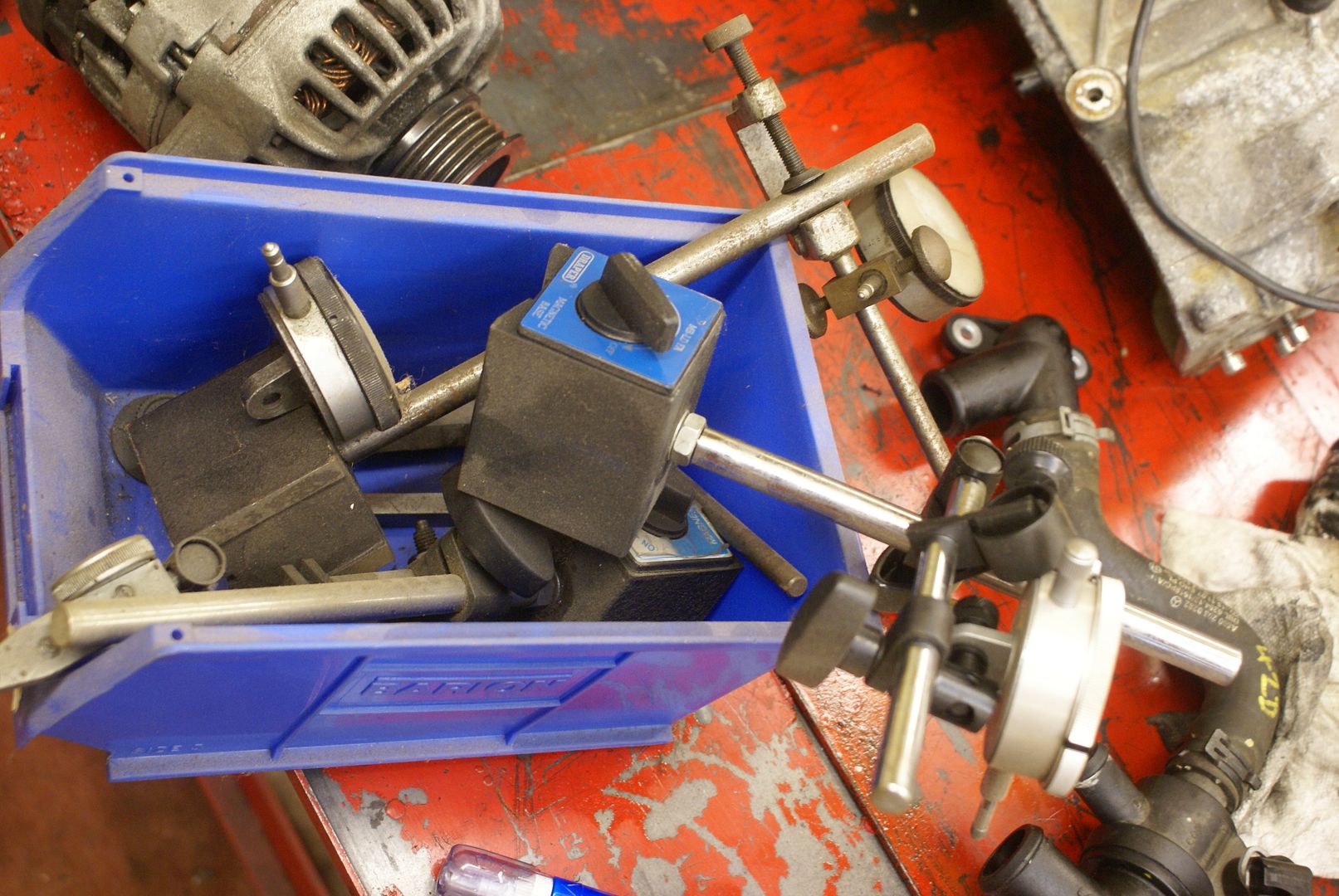
Okay, the Chinese ones are not as good as the Eclipse ones but let’s face it, they are one 10th of the price and they are not one 10th of the quality.
So, what I decided to do was to align the gearbox to the engine in exactly the same way that I would have aligned clutch in a conventional setup and in a very similar way that you find Top Dead Centre on an engine. To do that, you put the DTI on the top of the piston and move the engine back and forwards until you find the central point. The crankshaft will actually move a few degrees either way with no movement being detected on the DTI as the crankshaft goes back into over centre. Therefore, the crank top dead is in the centre of that needle movement. That was how I lined up the engine and gearbox.
I put 2 DTIs on the gearbox adapter plate with one reading longitude and the other at 90° reading latitude. I moved the gearbox side to side and up and down in relation to the engine and noted the centre point. I then did the same side to side and noted the centre point. I made sure that each DTI remained in the same place. I figured it was now central. However, it was loose so it needed securing. I put a load of weight on the back of the gearbox to apply a little bit of friction, doublechecked the DTI to make sure they had not moved and then put a tack weld onto the top of each pillar where it touched the gearbox. When the 4 pillars were tacked in place, I put more tacks around each pillar (moving around as though tightening a cylinder head) before removing the assembly and welding in place. I now had an adapter which simply needed the periphery filling in with some 18 mm steel sheet and making pretty. I wanted to make sure that nothing moved so the steel sheet wasn’t fully welded tacked in position around the periphery, it was just tack welded at regular intervals. The whole adapter housing was then finished after a little bit of dressing, cleaning and painting.
Because of the way the engine to gearbox adapter is now to be fitted, and the fact that it is mostly bolted through from the front whereas before it was belted through from the back, a couple of the original mounting bolts (the top 10 in particular) cannot be used. I figured that as a Volkswagen beetle only had four 10 mm studs holding the engine in, there are already plenty of fasteners holding a gearbox in and the omission of a couple would make no difference.
There was a problem with the gearbox adapter plate wacompletely of my own making. For some strange reason I didn’t line up the periphery of the gearbox plate with the periphery of the engine plate and they were offset by about 20 mm. I haven’t got a clue why, brain fade, incompetence, whatever. I could have made it fit quite easily I know that it wouldn’t have been right so I decided to make another one. I altered the periphery of the plate slightly and was prepared to see how version 2 fits then I decided that I could probably make a need to job with what I have. We shall see. However what it did was give me the opportunity to put the gearbox in place and to see how much side to side and opened down lateral play there is using my mandrel which goes at the centre of the gearbox input shaft. My guess is that as you simply put the gearbox in place with the mandrel lining everything up, it is pretty much central. It is possible to move it a few tenths of a millimetre in either direction and I am conscious that even a 10th of a millimetre out of line will put some strain on the bearing. We might just have to see how that goes. There is some play remember in the splines between the clutch driven plate and the gearbox input shaft.
What it’s also given me the opportunity to do is check the lengths of the clutch and the gearbox relative to the clutch basket. I measured these and measured these and measured these so they should be okay but we shall see. If the lengths are not correct, it’s simply a case of machining down the 4 “starter pillars” or, spacing them with washers. Trial and error. I am going to trial and error fit the clutch pushrod, with the clutch in place, and if it appears to be the right length, I will know that all my lengths are correct.
Quick as a flash, fit the clutch, fit the gearbox clutch pushrod. Job done
There it was, engine fitted to gearbox ready for a home to go to
Have you noticed how spindly the BMW K 100 frame looks when the engine is removed? I guess a lot of the “fear” you feel when you look at it is unfounded because the BMW engine weighs about the same as the smart engine and, as far as I am aware, frame breakage is do not seem to feature on BMW’s. However one thing that the BMW engine is not blessed (or should the word be “cursed”) with is vibration. Now, the Smart engine, being the three cylinder variety, is not going to vibrate like a dumper truck engine but nonetheless, there is going to be more vibration than BMW’s silky smooth 4 cylinder flat twin. I decided therefore to put some triangular braces in 3 mm steel that I thought were strategic points. The early Center stand is also known for breaking and my bike (a 1985 model) was no exception. It had clearly been welded previously and therefore it also underwent the triangular gusset strengthening procedure.
I don’t intend to use the centre stand a lot because there is a very adequate side stand but it is essential when, for example, changing the wheel. The last thing I wanted was for it to break and deposit the whole plot all over the workshop floor or pavement. BMW plastic is not cheap and nor is painting.
BMW thoughtfully mounted the battery onto rubber bobbins. BMW items are top-quality but they cost an arm and a leg and a kidney. Top-quality they may be but nonetheless, 3 of mine had fallen apart!. I therefore found something on eBay which were designed for something to do with racing cars. Cheap and do the job just as well.
I am going to use (hopefully) the original battery tray, I have no idea whether the battery size that it takes will be enough to start the Smart engine with its high compression. We shall see. Certainly, I’m going to have to buy the best quality and highest cold cranking amps battery that I can and it is suggested that a Glass Mat Technology battery would be small and do the job. We shall see.
I decided that beautifully made the BMW levers and controls and switchgear and twist grip are going to have to go. A friend of mine in the motorcycle club wanted them in any event. I figured that the indicator three button system with its self cancelling was just going to be a complication I didn’t need. In any event, I simply cannot get my head around having a right hand button to turn right and the left hand to turn left and another (on the right) cancel everything. BMW was so pleased with this system having used it for ever, they have now got rid of it!
I decided therefore to replace the switchgear with something a little more modern than that I was used to and I bought a set of Honda VFR switchgear from eBay for under 30 quid. In fact, I bought early switchgear was which was probably a bit of a mistake because it actually doesn’t look as nice as the later switchgear, but, I’m not about to spend another 30 quid at this stage. There is nothing wrong with it and it will be fine.
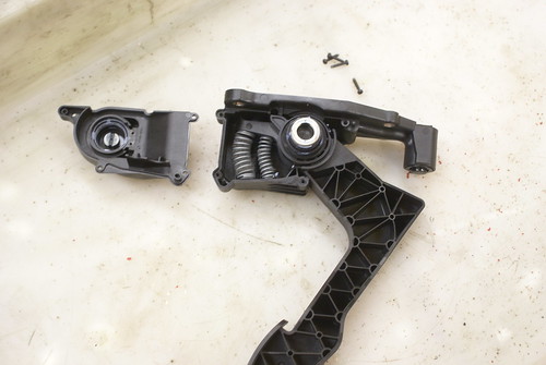
The twist grip has another feature which may (or may not) prove to be useful. It has 2 cables, a push and a pull. Therefore, when you close the throttle it is not just relying on the return spring and (certainly, on the motorcycle), it gives a silky smooth action. As I am going to have to adapt the throttle cables to pull on the Smart “fly by wire” throttle pedal (the only connection between the throttle pedal and the engine is electrical) there needs to be some kind of mechanical connection. I will need to find out where to locate the pedal assembly but that is another problem. There is actually plenty of room behind the headlamp and in the fairing as I don’t think it’s going to be that much of a problem but we shall see.
Here is the pedal assembly which I’m going to have to modify to be cable operated to activate the Fly by Wire throttle control. It isn’t a simple potentiometer it looks like something with a Hall Effect magnet inside so I think I’m going to use the central assembly and part of the pedal at some stage. Something for another day.
 DSC04239
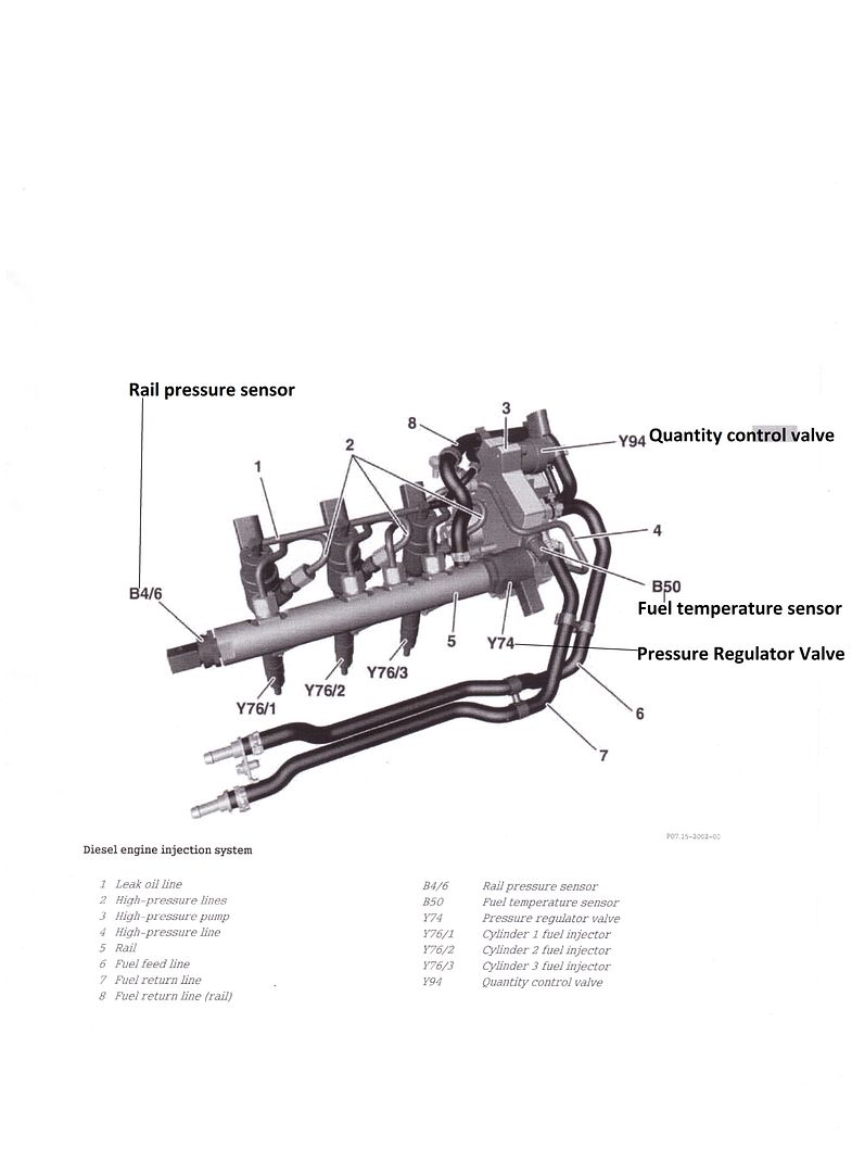
 I am a mechanical engineer, not a diesel engineer (why am I building a diesel engine motorcycle then?) and I had to do a little bit of research to actually find out which connector was which on the engine and which pipe went where. At first, it all seemed to be a bit of a mystery but the more I looked at it, the less connections there seemed to be and the easier it looked. We shall see whether that is the case when it comes to do the wiring. (We’re going to have to “see” a lot of things)
A chap on the Smartz forum kindly gave me a link to a page which described the Smart Common Rail injection system and actually named each of the parts. Fantastic.
Here is simplified wiring from the USA
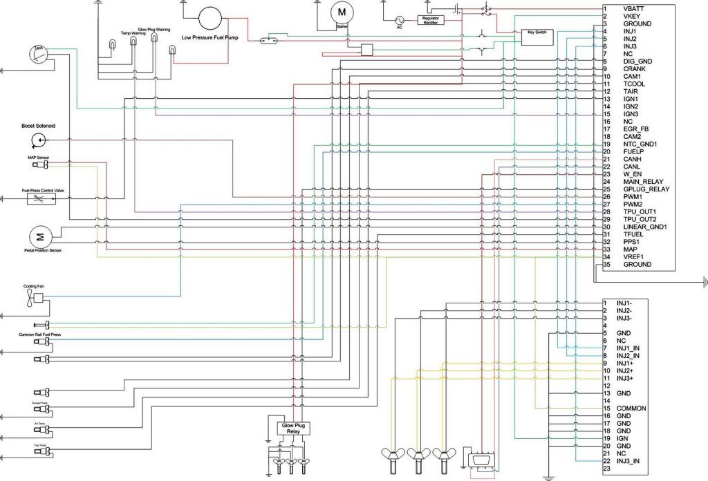
However the sensor names on the Merc data sheet page didn’t match up with the descriptions on the Specialist Components Ltd (SC) ECU Spreadsheet. I figured however that as I was spending well over a grand for the stand-alone SC ECU (which doesn’t have all the extra car connections in the loom which you don’t need on a motorcycle) the least SC could do was talk me through a description of each pin connection so that I could make an idiots guide, firstly for me, (number 1 idiot) and also for any of those who follow.
I will post future updates I get round to it.
I hope you’ve enjoyed reading and haven’t fallen asleep or lost the will to live.
